The practical answer.
Measure the finished device's current over complete operating cycles, then isolate one current path or firmware feature at a time. A low sleep plateau does not prove a low daily charge demand, and an instrument or debug connection can change the circuit being measured. Keep voltage, event timing, hardware revision and power-source configuration with the trace before blaming the coin cell or quoting a service-life figure.
- Capture rare events and retries as well as steady sleep current.
- Check whether the measurement setup adds voltage drop or an unintended power path.
- Turn current traces into conditional charge budgets, not guaranteed battery life.
- Keep primary cells isolated from charging paths during debugging.
Define the symptom in charge per event
An embedded product can meet its specified sleep current and still consume more charge than expected. The missing contribution may be a frequent wake event, a longer startup, a retry loop or a peripheral that is not consistently off. Ask what observation triggered the concern: a short laboratory trace, a returned device, a current reading on an engineering board or an actual controlled runtime test. These sources have different scope and should not be combined into an unsupported battery-life claim.
Begin with a reproducible hardware and firmware identity, an operating sequence and a defined power source. State which peripherals are connected and which communication conditions are present. Preserve the difference between a simulated supply and the selected primary coin cell. An ideal bench source can support a transient that a real cell and holder do not reproduce; a battery alone can make debugging less repeatable if its condition is not recorded. Use each source for a clear purpose.
Verify that the instrument is observing the intended circuit
Draw every power connection before collecting the baseline, including USB, programmer, serial adapter and sensor interfaces. Determine which devices can source a voltage onto the board. A measurement in the battery lead is incomplete if another connection supplies part of the load. Conversely, extra circuitry on a development board can raise measured consumption above the final product's demand. Investigate these paths rather than assuming that a connected debugger has no electrical effect.
Nordic's Power Profiler Kit II documentation distinguishes source mode from ampere-meter mode and describes synchronized current and logic observation. That supports an important measurement question: is the tool providing the supply or measuring an external source? Follow the tool's actual voltage, current and wiring limits. Its availability does not prove that any particular circuit has been measured correctly, nor is its instrument range a permitted load rating for a coin battery.
Check voltage burden and time resolution
A current measurement can influence the operating voltage through the measurement path and wiring. If the device behaves differently when the instrument is inserted, record voltage at the device as well as at the source. Do not assume that a reset during a pulse proves poor cell capacity. The supply path, contact arrangement and measurement method may be contributing. Use appropriate instruments and a controlled setup that can resolve the events relevant to the circuit.
A slow display can hide brief activity, while a short acquisition can miss infrequent events. Decide the necessary observation duration from the device behavior: periodic sensing, advertising, joining, retries, housekeeping and user action may occur at different intervals. An average without its acquisition window is incomplete. Preserve the original trace and event markers so another reviewer can see whether the captured cycle represents normal service or a special laboratory state.
| Change | Record before/after | Question answered |
|---|---|---|
| Remove an external interface safely | Current and device supply voltage | Was it powering or loading the circuit? |
| Disable one firmware feature | Same observation interval and event markers | Which activity contributes charge? |
| Change measurement range or tool | Burden and transient capture | Did the setup alter behavior? |
| Change a peripheral population | Board revision and disconnected path | Is off-state current in that branch? |
| Repeat at another approved condition | Temperature and source condition | Does the result depend on environment? |
Integrate the full cycle instead of reading the lowest plateau
For an invented planning example, assume a device spends 4 ms at 12 mA once every sixty seconds and the remaining 59.996 seconds at 2 microamps. The average is approximately 2.80 microamps: add 12 mA times 0.004 s and 0.002 mA times 59.996 s, then divide by sixty seconds. That corresponds to about 0.0672 mAh per day. These are hypothetical inputs, not Jetray battery measurements or a validated application profile.
Now suppose that same active event happens once per second. With 0.996 seconds at 2 microamps and 0.004 seconds at 12 mA, the average becomes approximately 50 microamps, or 1.20 mAh per day. The sleep plateau has not changed. The frequency of activity has changed the daily charge budget by nearly eighteen times. This is why firmware event counts and recovery behavior can matter more than a small improvement in a carefully selected sleep screenshot.
Look for retries and state transitions
Compare the normal connected state with the permitted conditions that cause repeated work. A device unable to communicate may retry; a sensor can require a longer initialization; a supply disturbance can restart a boot sequence. Do not assume that the best laboratory link represents every deployment. Record the state and cause of each event with the current trace, while keeping the test within the equipment's approved operating conditions.
Useful engineering questions include whether a retry has a limit, whether the device eventually returns to sleep and what happens after a low-voltage reset. These are firmware and system questions rather than coin-cell catalogue attributes. A more expensive cell is not a substitute for resolving an unbounded activity loop. Equally, a corrected firmware profile still needs evaluation with the selected cell, contact arrangement, temperature and device voltage requirements.
Build an off-state leakage budget
List the branches that remain connected when the processor sleeps: sensing dividers, regulator quiescent demand, pull networks, switching components, protection or isolation parts, memory and supporting capacitors. Compare documented behavior at the actual voltage and temperature, then measure the assembled board. A typical datasheet figure is not automatically a worst-case value, and a component's room-temperature result does not establish its behavior across the whole product environment.
Use controlled feature or branch isolation to test hypotheses. Change one factor at a time and retain the original result. If a clean prototype and an assembled unit differ, examine their actual circuit populations and process history instead of assigning the difference to contamination without evidence. A root-cause report should distinguish a measured contribution from a plausible explanation that has not been isolated. That distinction also makes supplier discussions more productive.
Use a charge budget without promising service life
Summing charge demand is a useful design tool, but it is only one part of battery evaluation. The battery capacity rating has its own conditions and endpoint. Device function also depends on voltage during the relevant event, contact behavior, environment and storage. TI's coin-cell white paper demonstrates that the interaction between load and a buffering capacitor can matter; its published experiment does not establish a universal pulse limit or a performance percentage for another device.
Keep the budget separated into measured portions, specified bounds and unmeasured assumptions. For example, label a trace as representing one firmware scenario rather than normal lifetime operation. Identify missing cold-condition, long-storage or rare-event evidence where relevant to the intended use. This prevents a neat spreadsheet result from becoming a guaranteed replacement interval before the product-level verification supports it. An honest range of uncertainty is more useful to an OEM buyer than an unjustified exact date.
Give sourcing a circuit requirement rather than a generic CR2032 request
Provide the selected manufacturer/model if known, measured demand profile, voltage requirements and mounting arrangement. Include the operating states that produced the largest charge contribution or lowest useful rail voltage. Jetray's CR2032 and CR2025 entries are reference-format inquiry pages, not proof of stocked or interchangeable branded products. Their common nominal diameter does not resolve the electrical or holder design.
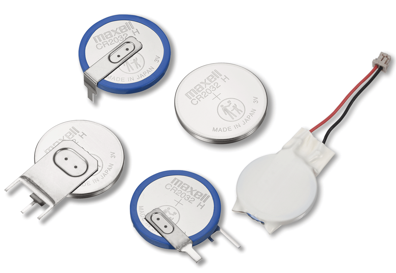
Request the exact offered cell specification and relevant performance information, then connect the approved choice to the tested circuit version. Do not infer Jetray manufacture or brand authorization from the Maxell family image used on the site. The useful handover combines a reproducible device trace with an identified supply proposal, not a generic marketing claim that a coin cell is suitable for ultra-low-power equipment.
- Freeze hardware, firmware, source and external-interface conditions.
- Verify the complete power path and the instrument's effect on device voltage.
- Capture full cycles plus infrequent permitted events and retries.
- Integrate charge and label the measurement window and assumptions.
- Isolate one branch or feature at a time while preserving prior traces.
- Confirm the final circuit with the specific proposed cell and mounting arrangement.
Frequently asked questions
Is a low sleep reading enough to predict battery life?
No. Count activity, retries and other current paths over representative time. Then evaluate useful voltage and the selected cell's documented conditions.
Can I measure the device while it is connected to USB?
Only if the setup accounts for every power path. Determine whether USB or another interface supplies or loads the circuit; label the measurement scope accordingly.
Should a primary coin cell be connected to an active charging path for testing?
No. Primary lithium cells are not rechargeable. Review isolation and possible reverse current before combining the circuit with other sources, using the selected manufacturer's instructions.
Sources & further reading
- Nordic Semiconductor PPK2 getting started: measurement and source modes ↗
- TI SWRA349: Coin cells and peak current draw ↗
- Panasonic primary lithium technical handbook ↗
AI-assisted embedded-device education, with hypothetical calculations and an editorial debugging workflow. No engineer biography, Jetray laboratory trace, cell stock, brand authorization or guaranteed runtime is claimed.
Prepared for the coin cell batteries collection. General engineering guidance does not replace a model-specific datasheet or application validation. Source review: 5 November 2026.